Datasheet Download — NEC
| Номер произв | C2335 | ||
| Описание | 2SC2335 | ||
| Производители | NEC | ||
| логотип | |||
|
1Page
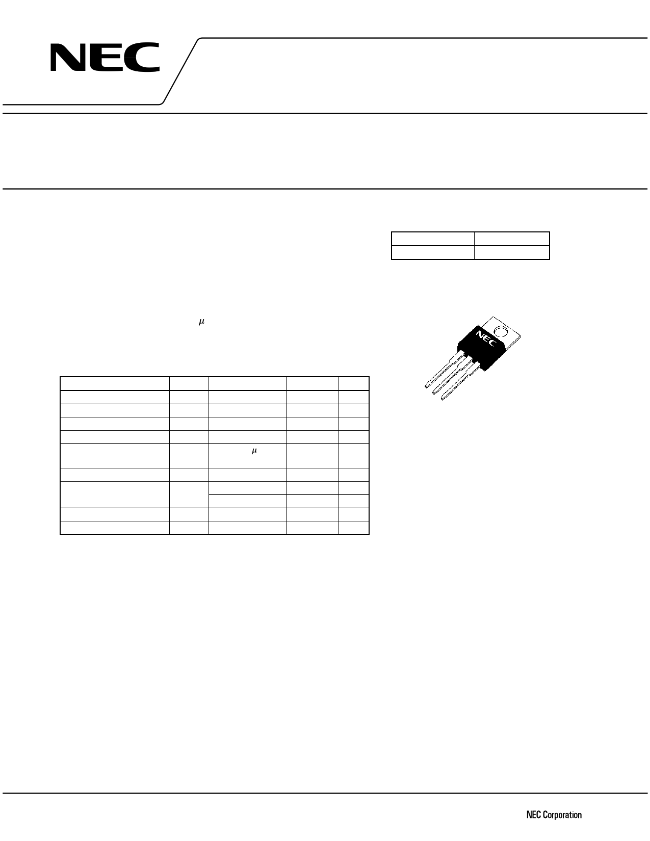
www.DataSheet4U.com • Low collector saturation voltage: VCE(sat) = 1.0 V MAX. @IC = 3.0 A • Fast switching speed: tf = 1.0 µs MAX. @IC = 3.0 A • Wide base reverse-bias SOA: VCEX(SUS)1 = 450 V MIN. @IC = 3.0 A ABSOLUTE MAXIMUM RATINGS (TA = 25°C) Parameter VCBO VCEO VEBO IC(DC) IC(pulse) IB(DC) PT Tj Tstg Conditions PW ≤ 300 µs, duty cycle ≤ 10% TC = 25°C TA = 25°C Ratings −55 to +150 A °C °C ORDERING INFORMATION 219928
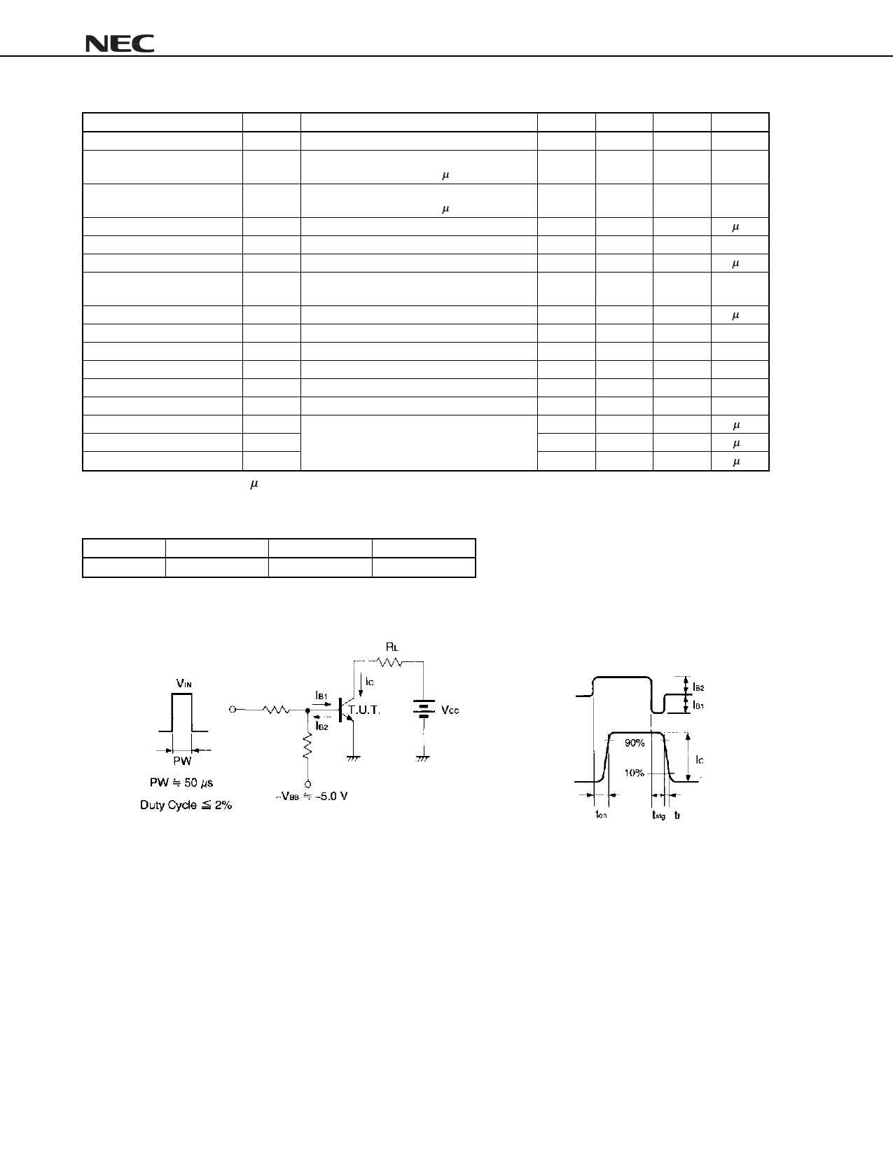
ELECTRICAL CHARACTERISTICS (TA = 25°C) Parameter VCEO(SUS) VCEX(SUS)1 VCEX(SUS)2 IC = 3.0 A, IB1 = 0.6 A, L = 1 mH IC = 3.0 A, IB1 = −IB2 = 0.6 A, VBE(OFF) = −5.0 V, L = 180 µH, clamped IC = 6.0 A, IB1 = 2.0 A, −IB2 = 0.6 A, VBE(OFF) = −5.0 V, L = 180 µH, clamped Collector cutoff current ICBO ICER ICEX1 ICEX2 VCB = 400 V, IE = 0 A VCE = 400 V, RBE = 51 Ω, TA = 125°C VCE = 400 V, VBE(OFF) = −1.5 V VCE = 400 V, VBE(OFF) = −1.5 V, TA = 125°C Emitter cutoff current IEBO hFE1 hFE2 hFE3 VCE(sat) VBE(sat) ton tstg tf VEB = 5.0 V, IC = 0 A VCE = 5.0 V, IC = 0.1 ANote VCE = 5.0 V, IC = 1.0 ANote VCE = 5.0 V, IC = 3.0 ANote IC = 3.0 A, IB = 0.6 ANote IC = 3.0 A, IB = 0.6 ANote IC = 3.0 A, RL = 50 Ω, IB1 = −IB2 = 0.6 A, VCC ≅ 150 V Refer to the test circuit. Note Pulse test PW ≤ 350 µs, duty cycle ≤ 2% hFE CLASSIFICATION Marking hFE2 M SWITCHING TIME (ton, tstg, tf) TEST CIRCUIT 2SC2335 µA mA µA mA µA V µs µs µs Base current 2 Data Sheet D14861EJ2V0DS
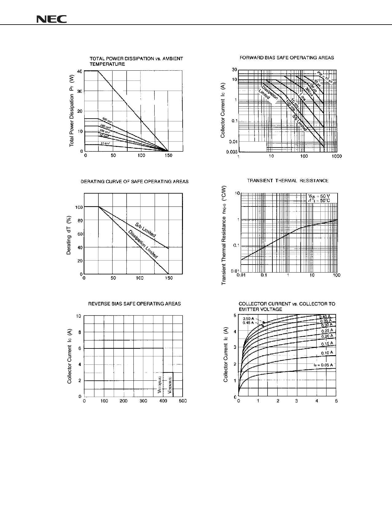
TYPICAL CHARACTERISTICS (TA = 25°C) PP DOXPLQXP ERDUG $PELHQW 7HPSHUDWXUH 7$ °& 2SC2335 &ROOHFWRU WR (PLWWHU 9ROWDJH 9&( 9 &DVH 7HPSHUDWXUH 7& °& 3XOVH :LGWK 3: PV &ROOHFWRU WR (PLWWHU 9ROWDJH 9&( 9 &ROOHFWRU WR (PLWWHU 9ROWDJH 9&( 9 Data Sheet D14861EJ2V0DS |
|||
| Всего страниц | 6 Pages | ||
| Скачать PDF |
Аналоги
Транзисторов которые были бы полным аналогом S9013 нет, но можно попытаться заменить его на такие зарубежные устройства:
- 2SC1008;
- KSC1008;
- KSP42;
- KSP43;
- MPSA42;
- MPSA43;
- MPSW05;
- ZTX457.
При замене нужно быть осторожным и перед принятием решения ознакомиться с технической документацией и после этого решать, подойдёт ли данный конкретный транзистор для замены. В качестве аналога также можно использовать отечественный КТ580, но он имеет другую распиновку. Также вместо S9013 можно попытаться установить КТ680, но к него немного другие параметры. Имеется также комплементарной пара – S9012.
IRF640NPBF Datasheet (PDF)
0.1. irf640nlpbf irf640npbf irf640nspbf.pdf Size:336K _international_rectifier
PD — 95046AIRF640NPbFIRF640NSPbFl Advanced Process Technology IRF640NLPbFl Dynamic dv/dt RatingHEXFET Power MOSFETl 175C Operating Temperaturel Fast SwitchingDVDSS = 200Vl Fully Avalanche Ratedl Ease of Parallelingl Simple Drive Requirements RDS(on) = 0.15Gl Lead-FreeDescriptionID = 18AFifth Generation HEXFET Power MOSFETs fromSInternational Rectif
0.2. irf640npbf irf640nspbf irf640nlpbf.pdf Size:336K _infineon
PD — 95046AIRF640NPbFIRF640NSPbFl Advanced Process Technology IRF640NLPbFl Dynamic dv/dt RatingHEXFET Power MOSFETl 175C Operating Temperaturel Fast SwitchingDVDSS = 200Vl Fully Avalanche Ratedl Ease of Parallelingl Simple Drive Requirements RDS(on) = 0.15Gl Lead-FreeDescriptionID = 18AFifth Generation HEXFET Power MOSFETs fromSInternational Rectif
7.1. irf640n.pdf Size:155K _international_rectifier
PD — 94006IRF640NIRF640NSIRF640NL Advanced Process TechnologyHEXFET Power MOSFET Dynamic dv/dt RatingD 175C Operating TemperatureVDSS = 200V Fast Switching Fully Avalanche RatedRDS(on) = 0.15 Ease of ParallelingG Simple Drive RequirementsDescriptionID = 18AFifth Generation HEXFET Power MOSFETs from SInternational Rectifier utilize advanced processi
7.2. irf640ns.pdf Size:228K _inchange_semiconductor
Isc N-Channel MOSFET Transistor IRF640NSFEATURESWith TO-263( DPAK ) packagingHigh speed switchingLow gate input resistanceStandard level gate driveEasy to use100% avalanche testedMinimum Lot-to-Lot variations for robust deviceperformance and reliable operationAPPLICATIONSPower supplySwitching applicationsABSOLUTE MAXIMUM RATINGS(T =25)a
7.3. irf640nl.pdf Size:244K _inchange_semiconductor
Isc N-Channel MOSFET Transistor IRF640NLFEATURESWith TO-262 packagingHigh speed switchingLow gate input resistanceStandard level gate driveEasy to use100% avalanche testedMinimum Lot-to-Lot variations for robust deviceperformance and reliable operationAPPLICATIONSPower supplySwitching applicationsABSOLUTE MAXIMUM RATINGS(T =25)aSYMBOL PAR
7.4. irf640n.pdf Size:245K _inchange_semiconductor
isc N-Channel MOSFET Transistor IRF640NIIRF640NFEATURESStatic drain-source on-resistance:RDS(on) 150mEnhancement modeFast Switching Speed100% avalanche testedMinimum Lot-to-Lot variations for robust deviceperformance and reliable operationDESCRITION Efficient and reliable device for use in a wide variety of applicationsABSOLUTE MAXIMUM RATINGS(T
Другие MOSFET… SMG2301
, SMG2301P
, SMG2302
, SMG2302N
, SMG2305
, SMG2305P
, SMG2305PE
, SMG2306A
, IRF1404
, SMG2306NE
, SMG2310A
, SMG2310N
, SMG2314N
, SMG2314NE
, SMG2318N
, SMG2319P
, SMG2321P
.
2SC2335F Datasheet (PDF)
0.1. 2sc2335f.pdf Size:201K _inchange_semiconductor
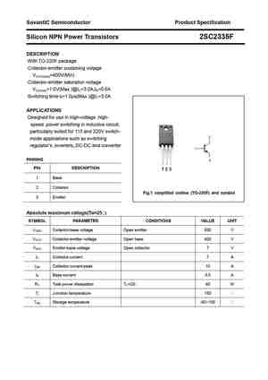
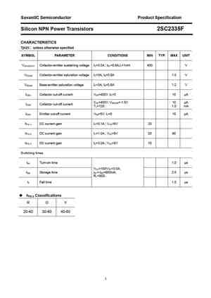
SavantIC Semiconductor Product Specification Silicon NPN Power Transistors 2SC2335F DESCRIPTION With TO-220F package Collector-emitter sustaining voltage VCEO(sus)=400V(Min) Collector-emitter saturation voltage VCE(sat)=1.0V(Max.)@IC=3.0A,IB=0.6A Switching time-tf=1.0s(Max.)@IC=3.0A APPLICATIONS Designed for use in high-voltage ,high- speed ,power switching
7.1. 2sc2335.pdf Size:118K _nec
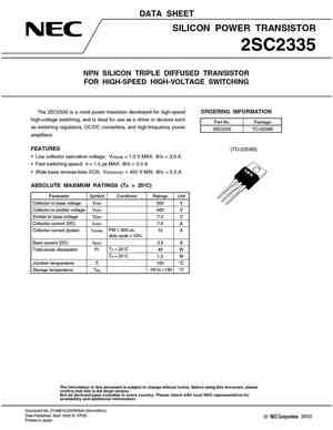
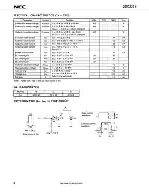
DATA SHEETSILICON POWER TRANSISTOR2SC2335NPN SILICON TRIPLE DIFFUSED TRANSISTORFOR HIGH-SPEED HIGH-VOLTAGE SWITCHINGThe 2SC2335 is a mold power transistor developed for high-speed ORDERING INFORMATIONhigh-voltage switching, and is ideal for use as a driver in devices suchPart No. Packageas switching regulators, DC/DC converters, and high-frequency power2SC2335 TO-220ABamplif
7.2. 2sc2335.pdf Size:131K _mospec
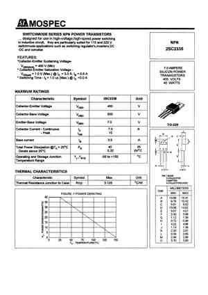
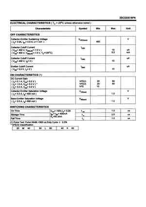
AAA
7.3. 2sc2335.pdf Size:205K _jmnic
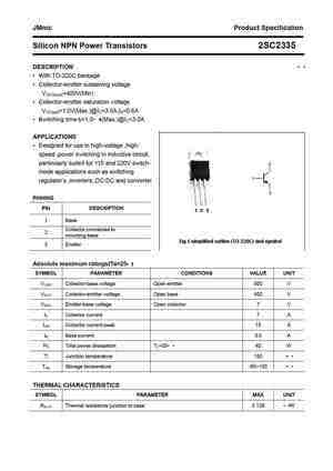
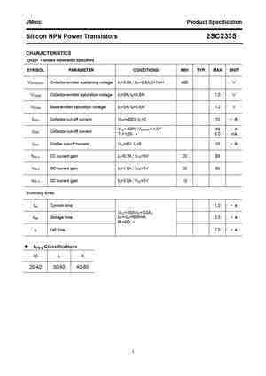
JMnic Product Specification Silicon NPN Power Transistors 2SC2335 DESCRIPTION With TO-220C package Collector-emitter sustaining voltage VCEO(sus)=400V(Min) Collector-emitter saturation voltage VCE(sat)=1.0V(Max.)@IC=3.0A,IB=0.6A Switching time-tf=1.0s(Max.)@IC=3.0A APPLICATIONS Designed for use in high-voltage ,high- speed ,power switching in inductive cir
7.4. 2sc2335.pdf Size:203K _inchange_semiconductor
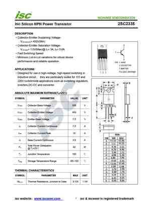
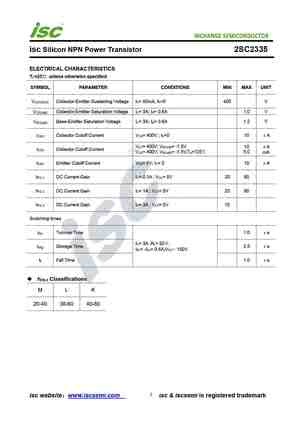
isc Silicon NPN Power Transistor 2SC2335DESCRIPTIONCollector-Emitter Sustaining Voltage-: V = 400V(Min)CEO(SUS)Collector-Emitter Saturation Voltage-: V = 1.0V(Max)@ I = 3A, I = 0.6ACE(sat) C BFast Switching SpeedMinimum Lot-to-Lot variations for robust deviceperformance and reliable operationAPPLICATIONSDesigned for use in high-voltage, high-speed switching in
Другие транзисторы… 2SC4360
, 2SC4361
, 2SC4362
, 2SC4363
, 2SC4364
, 2SC4365
, 2SC4366
, 2SC4367
, D882
, 2SC4369
, 2SC437
, 2SC4370
, 2SC4371
, 2SC4372
, 2SC4373
, 2SC4374
, 2SC4375
.
Модификации и группы транзистора C3198
| Модель | PC | UCB | UCE | UBE | IC | TJ | fT | CC | hFE ٭ | NF (типовое) dB | Корпус |
|---|---|---|---|---|---|---|---|---|---|---|---|
| C3198 | 0,625 | 60 | 50 | 5 | 0,15 | 150 | 80 | 3,5 | 25…700 | ≤ 10 | TO-92 |
| C SC3198 (O, Y, GR, BL) | 0,625 | 60 | 50 | 5 | 0,15 | 125 | 80 | 3,5 | 25…700 | ≤ 10 | TO-92 |
| FTC3198 | 0,625 | 60 | 50 | 5 | 0,15 | 150 | 80 | 3,5 | 25…700 | ≤ 10 | TO-92 |
| KTC3198 | 0,625 | 60 | 50 | 5 | 0,15 | 150 | 80 | 3,5 | 25…700 | ≤ 10 | TO-92 |
| KTC3198A | 0,4 | 60 | 50 | 5 | 0,15 | 150 | 80 | 2 | 25…700 | 1 | TO-92 |
| KTC3198L ٭٭ | 0,625 | 60 | 50 | 5 | 0,15 | 150 | 80 | 2 | 25…700 | 0,5 (1) 0,2 (2) | TO-92 |
٭ — диапазон значений параметра hFE разделяется производителями во всех модификациях на четыре подгруппы (O, Y, GR, BL).
٭٭ — значения коэффициента шума транзистора KTC3198L: 0,5 (1) и 0,2 (2) определены при частотах сигнала соответственно 100 Гц и 1 кГц.
Основные электрические параметры
Значения напряжения и тока в таблице соответствуют температуре окружающей среды +25°C.
| Обозначение | Параметр | Условия измерения | Величина | Ед. изм. |
|---|---|---|---|---|
| V(BR)CBO | Напряжение пробоя коллектор-база | IC=1мA, IE=0 | 60 | В |
| V(BR)CЕO | Напряжение пробоя коллектор-эмиттер | IC=100мкA, IВ=0 | 50 | В |
| V(BR)ЕBO | Напряжение пробоя эмиттер-база | IЕ=1мкA, IС=0 | 5 | В |
| ICBO | Ток отсечки коллектора | VCB=60В, IE=0 | 0,1 | мкА |
| ICЕO | Ток отсечки коллектора | VCЕ=45В, IE=0 | 0,1 | мкА |
| IЕВО | Ток отсечки эмиттера | VЕВ=45В, IС=0 | 0,1 | мкА |
| hFE(1) | Коэффициент усиления по постоянному току | VCE=6В, IC=1мA | 70…700 | |
| hFE(2) | VCE=6В, IC=0.1мA | 40 | ||
| VCE(sat) | Напряжение насыщения коллектор-эмиттер | IC=100мA, IB=10мA | 0,3 | В |
| VBE(sat) | Напряжение насыщения база-эмиттер | IC=100мA, IB=10мA | 1 | В |
| fT | Граничная частота коэффициента передачи тока | VCE=6В, IC=10mA, f=30МГц | 200 | МГц |
| Cob | Выходная емкость коллектора | VCB=10В, IE=0, f=1МГц | 3 | пФ |
| NF | Уровень шума | VCE=6В, IC=0.1мА RG=10кОм, f=1МГц | 10 | dB |
