
IRFP4110PBF Datasheet PDF — International Rectifier
| Part Number | IRFP4110PBF | |
| Description | HEXFET Power MOSFET | |
| Manufacturers | International Rectifier | |
| Logo | ||
|
There is a preview and IRFP4110PBF download ( pdf file ) link at the bottom of this page. Total 8 Pages |
|
Preview 1 page
No Preview Available !
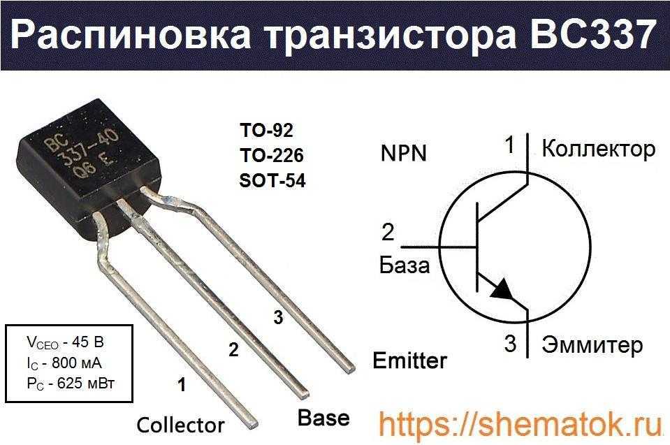
PD — 97311 l High Efficiency Synchronous Rectification in SMPS l Uninterruptible Power Supply l High Speed Power Switching l Hard Switched and High Frequency Circuits Benefits l Improved Gate, Avalanche and Dynamic dv/dt Ruggedness l Fully Characterized Capacitance and Avalanche SOA l Enhanced body diode dV/dt and dI/dt Capability IRFP4110PbF HEXFETPower MOSFET VDSS RDS(on) typ. max. ID (Silicon Limited) ID (Package Limited) 100V 3.7m 4.5m 180A c 120A GD G S TO-247AC Absolute Maximum Ratings ID @ TC = 25°C ID @ TC = 100°C ID @ TC = 25°C IDM PD @TC = 25°C Continuous Drain Current, VGS @ 10V (Silicon Limited) Continuous Drain Current, VGS @ 10V (Silicon Limited) Continuous Drain Current, VGS @ 10V (Wire Bond Limited) Pulsed Drain Current d Maximum Power Dissipation VGS Gate-to-Source Voltage dv/dt TJ TSTG Peak Diode Recovery f Operating Junction and EAS (Thermally limited) Single Pulse Avalanche Energy e IAR Avalanche Current d EAR Repetitive Avalanche Energy g Thermal Resistance RθJC Junction-to-Case k RθCS Case-to-Sink, Flat Greased Surface RθJA Junction-to-Ambient j www.irf.com 180c 130c 120 10lbxin (1.1Nxm) 190 1http://www.Datasheet4U.com 03/03/08 |
|
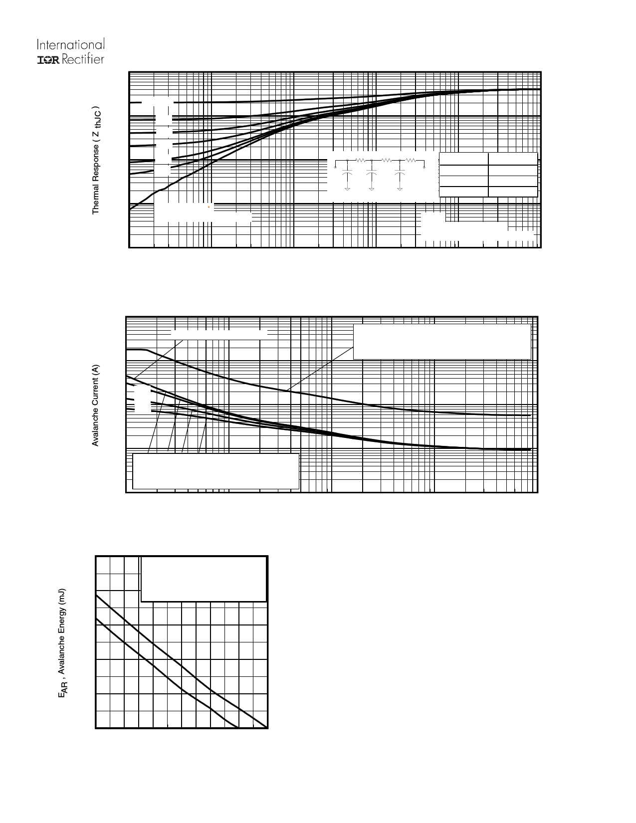
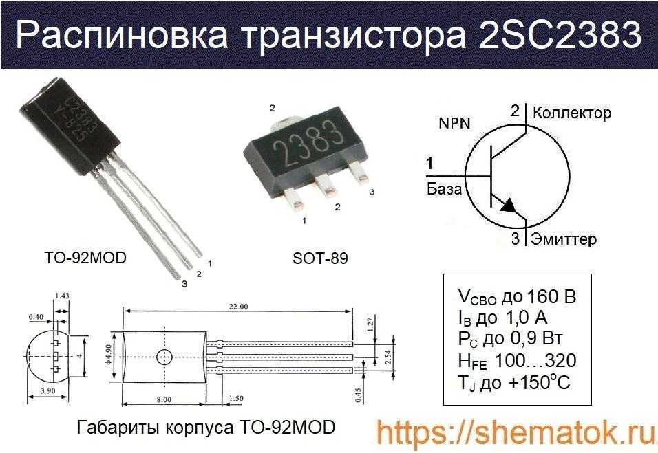
0.1 0.20 0.10 τJ τJ τ1 τ1 R 1R 1 Ci = τiRi Ci = τiRi R 2R 2 τ2 τ2 R3R3 Ri (°C/W) τCτC 0.09876251 τ3τ3 0.2066697 0.09510464 τi (sec) 0.000111 Fig 13. Maximum Effective Transient Thermal Impedance, Junction-to-Case 1000 pulsewidth, tav, assuming ∆ Tj = 150°C and Tstart =25°C (Single Pulse) pulsewidth, tav, assuming ∆Τ j = 25°C and Tstart = 150°C. Fig 14. Typical Avalanche Current vs.Pulsewidth 1.0E-01 250 Notes on Repetitive Avalanche Curves , Figures 14, 15: TOP 200 ID = 108A 150 excess of Tjmax. This is validated for every part type. 2. Safe operation in Avalanche is allowed as long asT jmax is not exceeded. 3. Equation below based on circuit and waveforms shown in Figures 16a, 16b. 4. PD (ave) = Average power dissipation per single avalanche pulse. 5. BV = Rated breakdown voltage (1.3 factor accounts for voltage increase 100 6. Iav = Allowable avalanche current. 7. ∆T = Allowable rise in junction temperature, not to exceTejmdax (assumed as 25°C in Figure 14, 15). 50 tav = Average time in avalanche. D = Duty cycle in avalanche = tav ·f ZthJC(D, tav) = Transient thermal resistance, see Figures 13) 25 50 75 100 125 150 175 PD (ave) = 1/2 ( 1.3·BV·Iav) = DT/ ZthJC Iav = 2DT/ [1.3·BV·Zth EAS (AR) = PD (ave)·tav Fig 15. Maximum Avalanche Energy vs. Temperature www.irf.com Preview 5 Page |
 IRFP4110PbF
|
On this page, you can learn information such as the schematic, equivalent, pinout, replacement, circuit, and manual for IRFP4110PBF electronic component. |
| Information | Total 8 Pages |
| Link URL | |
| Download |
Share Link :
Electronic Components Distributor
|
An electronic components distributor is a company that sources, stocks, and sells electronic components to manufacturers, engineers, and hobbyists. |
| SparkFun Electronics | Allied Electronics | DigiKey Electronics | Arrow Electronics |
| Mouser Electronics | Adafruit | Newark | Chip One Stop |
IRFP4110 Datasheet (PDF)
..1. Size:288K international rectifier irfp4110pbf.pdf
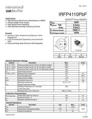

PD — 97311IRFP4110PbFApplicationsHEXFET Power MOSFETl High Efficiency Synchronous Rectification in SMPSl Uninterruptible Power Supply VDSS 100Vl High Speed Power SwitchingRDS(on) typ.3.7m:l Hard Switched and High Frequency Circuitsmax.4.5m:ID (Silicon Limited)180A cID (Package Limited)120ABenefitsl Improved Gate, Avalanche and Dynamic dv/dtRuggednessDl
..2. Size:288K infineon irfp4110pbf.pdf

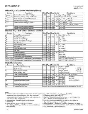
PD — 97311IRFP4110PbFApplicationsHEXFET Power MOSFETl High Efficiency Synchronous Rectification in SMPSl Uninterruptible Power Supply VDSS 100Vl High Speed Power SwitchingRDS(on) typ.3.7m:l Hard Switched and High Frequency Circuitsmax.4.5m:ID (Silicon Limited)180A cID (Package Limited)120ABenefitsl Improved Gate, Avalanche and Dynamic dv/dtRuggednessDl
..3. Size:243K inchange semiconductor irfp4110.pdf
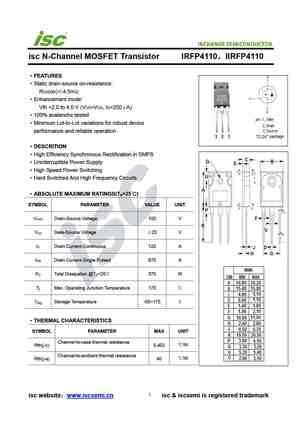

INCHANGE Semiconductorisc N-Channel MOSFET Transistor IRFP4110IIRFP4110FEATURESStatic drain-source on-resistance:RDS(on)4.5mEnhancement mode:Vth =2.0 to 4.0 V (VDS=VGS, ID=250A)100% avalanche testedMinimum Lot-to-Lot variations for robust deviceperformance and reliable operationDESCRITIONHigh Efficiency Synchronous Rectification in SMPSUninterr
0.1. Size:519K infineon auirfp4110.pdf

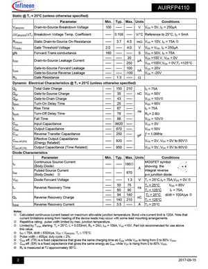
AUTOMOTIVE GRADE AUIRFP4110 HEXFET Power MOSFET Features Advanced Process Technology VDSS 100V DUltra Low On-Resistance RDS(on) typ. 3.7mEnhanced dV/dT and dI/dT capability 4.5mmax 175C Operating Temperature GID (Silicon Limited) 180A Fast Switching SRepetitive Avalanche Allowed up to Tjmax ID (Package Lim
8.1. Size:511K international rectifier irfp4127pbf.pdf

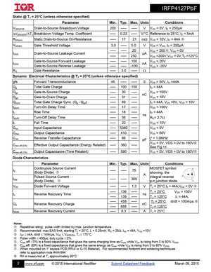
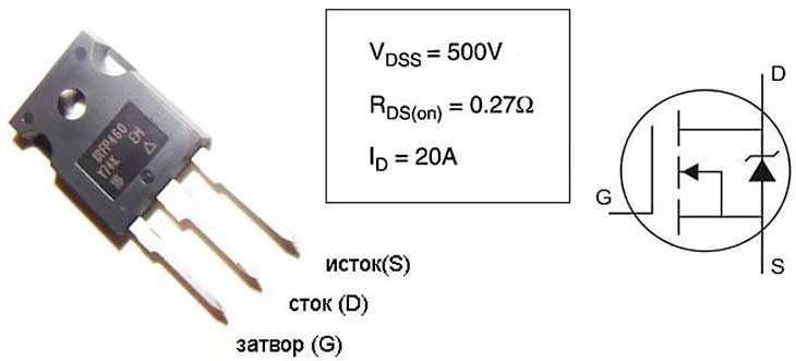
IRFP4127PbF HEXFET Power MOSFET Application High Efficiency Synchronous Rectification in SMPS DVDSS 200V Uninterruptible Power Supply High Speed Power Switching RDS(on) typ. 17m Hard Switched and High Frequency Circuits G 21mmax SID 75A Benefits Improved Gate, Avalanche and Dynamic dV/dt Ruggedness Fully Chara
8.2. Size:380K international rectifier irfp4137pbf.pdf


IRFP4137PbF HEXFET Power MOSFET Application High Efficiency Synchronous Rectification in SMPS DVDSS 300V Uninterruptible Power Supply High Speed Power Switching RDS(on) typ. 56m Hard Switched and High Frequency Circuits G 69mmax SID 38A Benefits Improved Gate, Avalanche and Dynamic dV/dt Ruggedness Fully Chara
8.3. Size:511K infineon irfp4127pbf.pdf
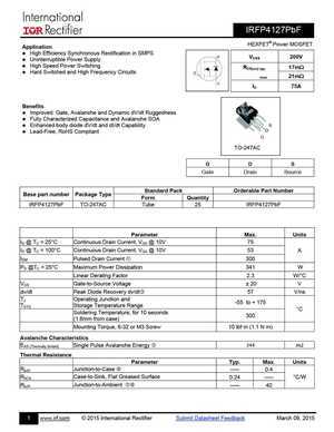

IRFP4127PbF HEXFET Power MOSFET Application High Efficiency Synchronous Rectification in SMPS DVDSS 200V Uninterruptible Power Supply High Speed Power Switching RDS(on) typ. 17m Hard Switched and High Frequency Circuits G 21mmax SID 75A Benefits Improved Gate, Avalanche and Dynamic dV/dt Ruggedness Fully Chara
8.4. Size:383K infineon irfp4137pbf.pdf
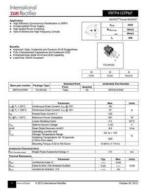
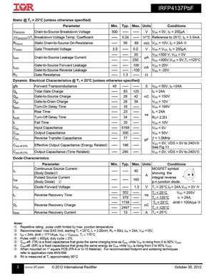
IRFP4137PbF HEXFET Power MOSFET Application High Efficiency Synchronous Rectification in SMPS DVDSS 300V Uninterruptible Power Supply High Speed Power Switching RDS(on) typ. 56m Hard Switched and High Frequency Circuits G 69mmax SID 38A Benefits Improved Gate, Avalanche and Dynamic dV/dt Ruggedness Fully Chara
8.5. Size:242K inchange semiconductor irfp4137.pdf

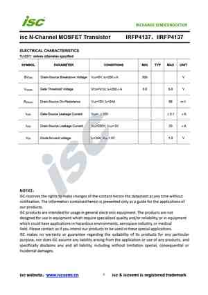
isc N-Channel MOSFET Transistor IRFP4137IIRFP4137FEATURESStatic drain-source on-resistance:RDS(on)69mEnhancement mode:100% avalanche testedMinimum Lot-to-Lot variations for robust deviceperformance and reliable operationDESCRITIONHigh Speed Power SwitchingABSOLUTE MAXIMUM RATINGS(T =25)aSYMBOL PARAMETER VALUE UNITV Drain-Source Voltage 300 V
8.6. Size:242K inchange semiconductor irfp4127.pdf


INCHANGE Semiconductorisc N-Channel MOSFET Transistor IRFP4127IIRFP4127FEATURESStatic drain-source on-resistance:RDS(on)21mEnhancement mode:100% avalanche testedMinimum Lot-to-Lot variations for robust deviceperformance and reliable operationDESCRITIONHigh Efficiency Synchronous Rectification in SMPSUninterruptible Power SupplyHigh Speed Power