
IRFB3607GPBF Datasheet PDF — International Rectifier
| Part Number | IRFB3607GPBF | |
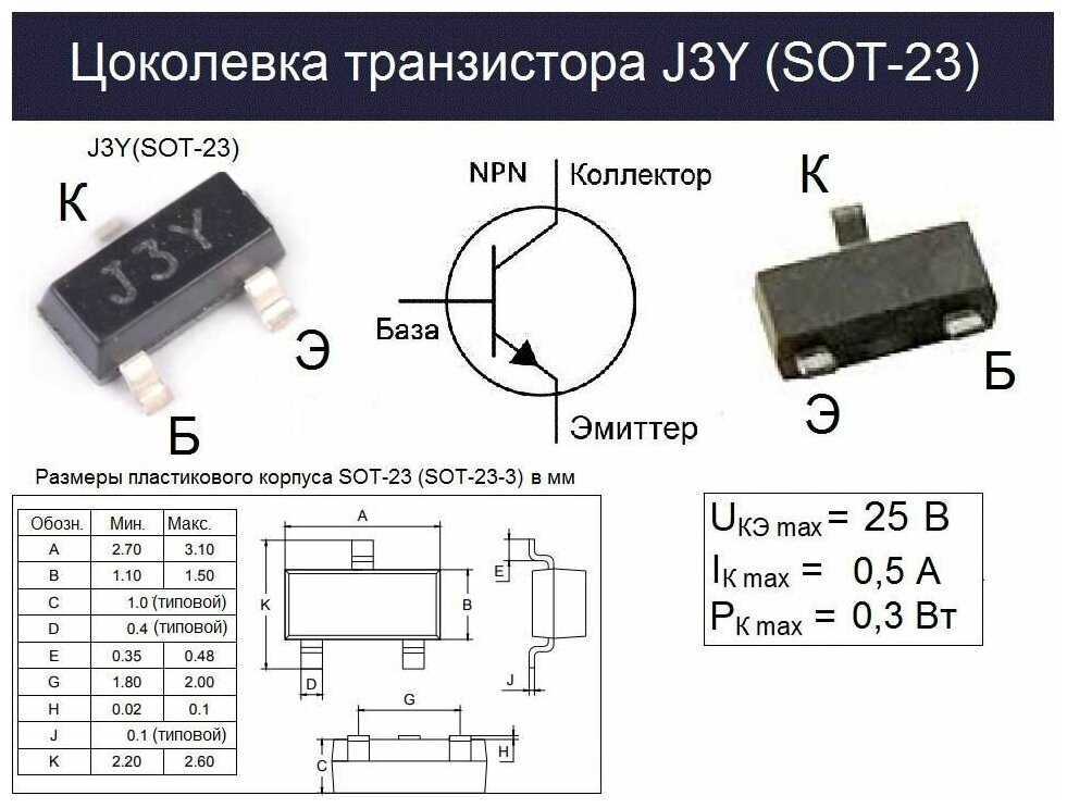
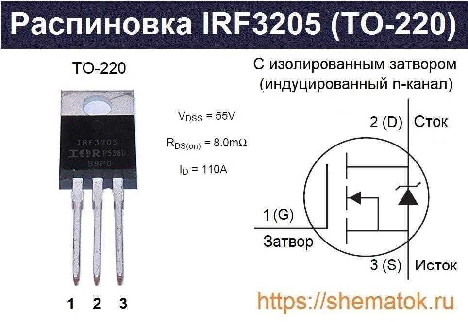
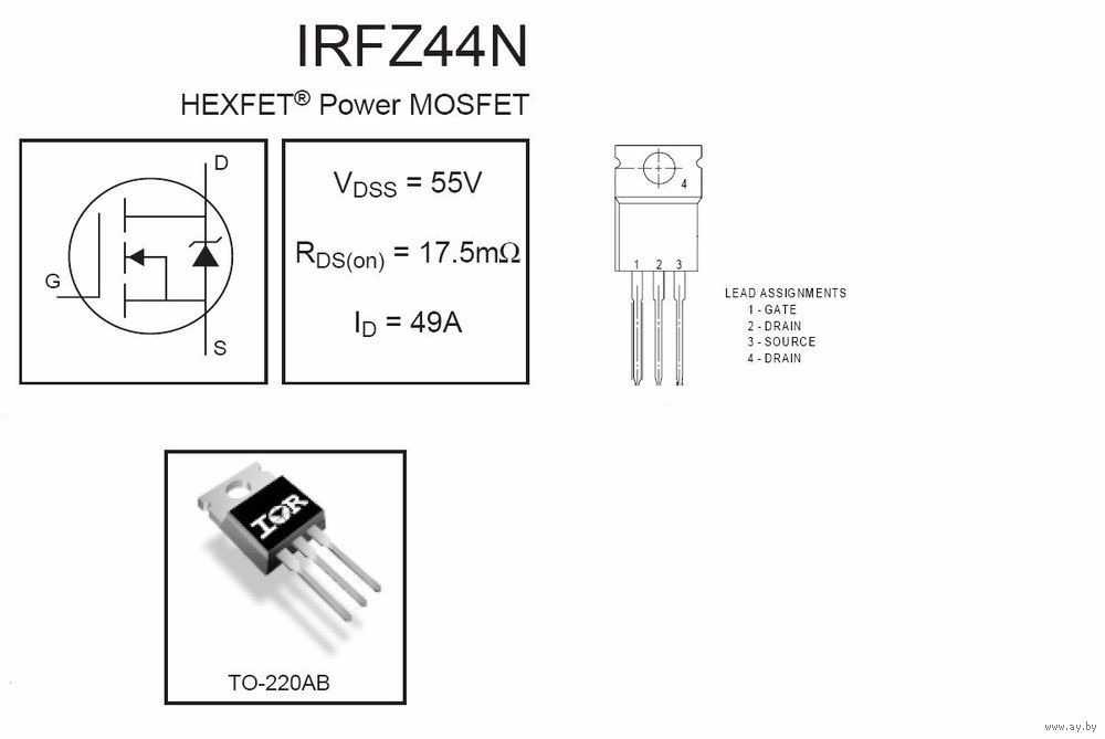
| Description | Power MOSFET ( Transistor ) | |
| Manufacturers | International Rectifier | |
| Logo | ||
|
There is a preview and IRFB3607GPBF download ( pdf file ) link at the bottom of this page. Total 8 Pages |
|
Preview 1 page
No Preview Available !
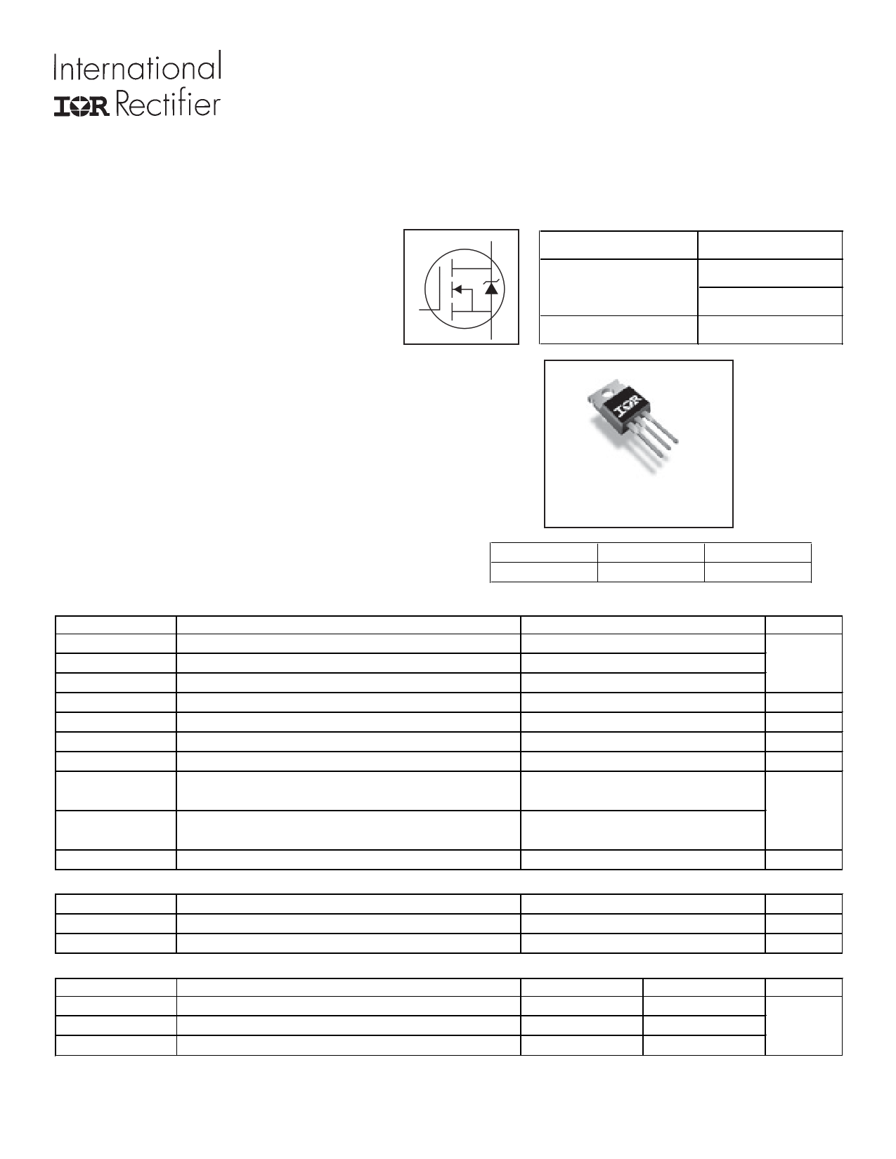
PD — 96329 l High Efficiency Synchronous Rectification in SMPS l Uninterruptible Power Supply l High Speed Power Switching l Hard Switched and High Frequency Circuits Benefits l Improved Gate, Avalanche and Dynamic dv/dt Ruggedness l Fully Characterized Capacitance and Avalanche SOA l Enhanced body diode dV/dt and dI/dt Capability l Lead-Free l Halogen-Free G ID @ TC = 25°C Continuous Drain Current, VGS @ 10V ID @ TC = 100°C IDM Continuous Drain Current, VGS @ 10V dPulsed Drain Current PD @TC = 25°C Maximum Power Dissipation Linear Derating Factor VGS dv/dt fPeak Diode Recovery TJ Operating Junction and TSTG Storage Temperature Range EAS (Thermally limited) IAR EAR eSingle Pulse Avalanche Energy ÃAvalanche Current gRepetitive Avalanche Energy Thermal Resistance jRθJC Junction-to-Case RθCS Case-to-Sink, Flat Greased Surface, TO-220 RθJA Junction-to-Ambient, TO-220 IRFB3607GPbF HEXFETPower MOSFET D VDSS RDS(on) typ. max. S ID 75V 7.34m 9.0m 80A 80 56 310 x x10lb in (1.1N m) 120 1http://www.Datasheet4U.com 08/12/10 |
|
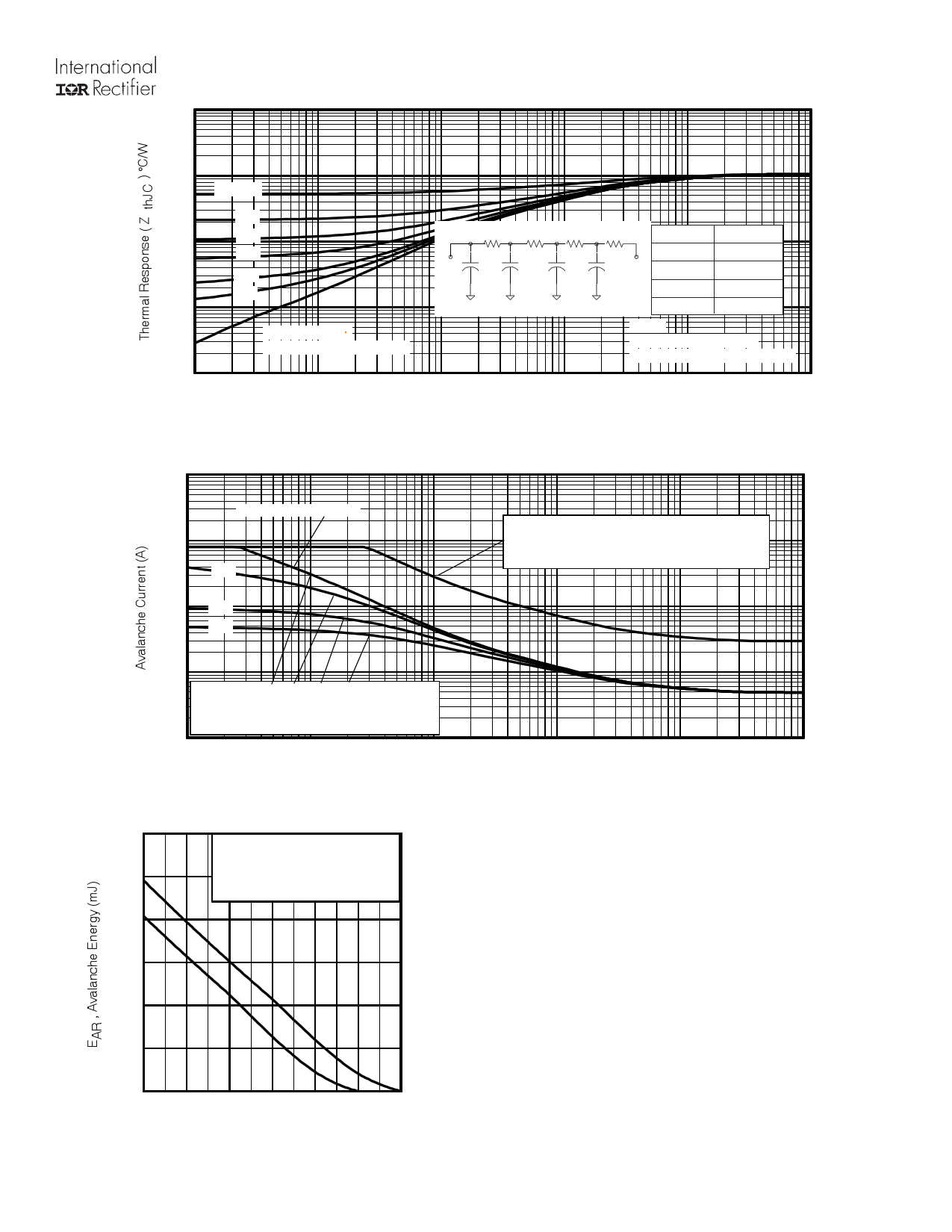
τJ τJ τ1 τ1 R1R1 R2R2 τ2 τ2 R3R3 τ3 τ3 R4R4 τCτ Ri (°C/W) τi (sec) 0.000003 τ4τ4 0.49731 0.001301 CiC= iτiRiiRi 0.26766 0.008693 Fig 13. Maximum Effective Transient Thermal Impedance, Junction-to-Case 1000 pulsewidth, tav, assuming ∆Tj = 150°C and Tstart =25°C (Single Pulse) pulsewidth, tav, assuming ∆Τ j = 25°C and Tstart = 150°C. Fig 14. Typical Avalanche Current vs.Pulsewidth 1.0E-01 excess of Tjmax. This is validated for every part type. 2. Safe operation in Avalanche is allowed as long asTjmax is not exceeded. 3. Equation below based on circuit and waveforms shown in Figures 16a, 16b. 4. PD (ave) = Average power dissipation per single avalanche pulse. 5. BV = Rated breakdown voltage (1.3 factor accounts for voltage increase 6. Iav = Allowable avalanche current. 7. ∆T = Allowable rise in junction temperature, not to exceTejmdax (assumed as 25°C in Figure 14, 15). tav = Average time in avalanche. D = Duty cycle in avalanche = tav ·f ZthJC(D, tav) = Transient thermal resistance, see Figures 13) 25 50 75 100 125 150 175 Fig 15. Maximum Avalanche Energy vs. Temperature PD (ave) = 1/2 ( 1.3·BV·Iav) = DT/ ZthJC Iav = 2DT/ [1.3·BV·Zth EAS (AR) = PD (ave)·tav www.irf.com Preview 5 Page |
 IRFB3607GPbF
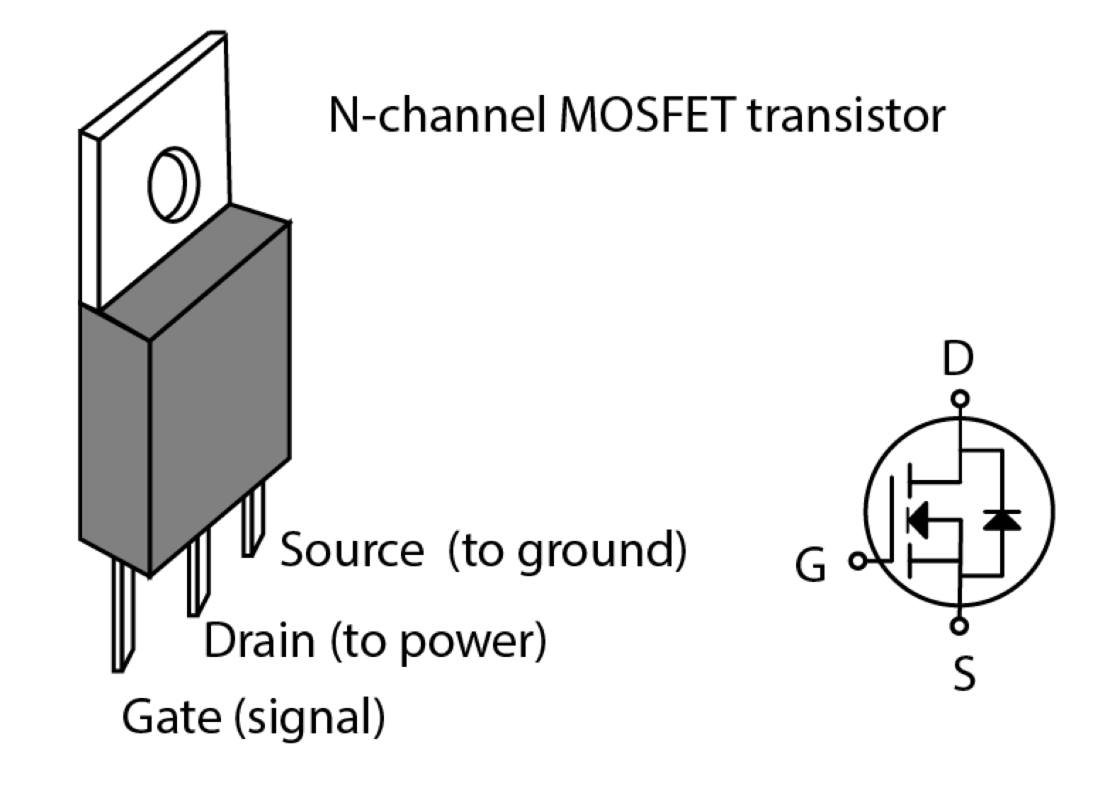

|
On this page, you can learn information such as the schematic, equivalent, pinout, replacement, circuit, and manual for IRFB3607GPBF electronic component. |
| Information | Total 8 Pages |
| Link URL | |
| Download |
Share Link :
Electronic Components Distributor
|
An electronic components distributor is a company that sources, stocks, and sells electronic components to manufacturers, engineers, and hobbyists. |
| SparkFun Electronics | Allied Electronics | DigiKey Electronics | Arrow Electronics |
| Mouser Electronics | Adafruit | Newark | Chip One Stop |