IRLR2905 Datasheet PDF — International Rectifier
| Part Number | IRLR2905 | |
| Description | Power MOSFET ( Transistor ) | |
| Manufacturers | International Rectifier | |
| Logo | ||
|
There is a preview and IRLR2905 download ( pdf file ) link at the bottom of this page. Total 10 Pages |
|
Preview 1 page
No Preview Available !
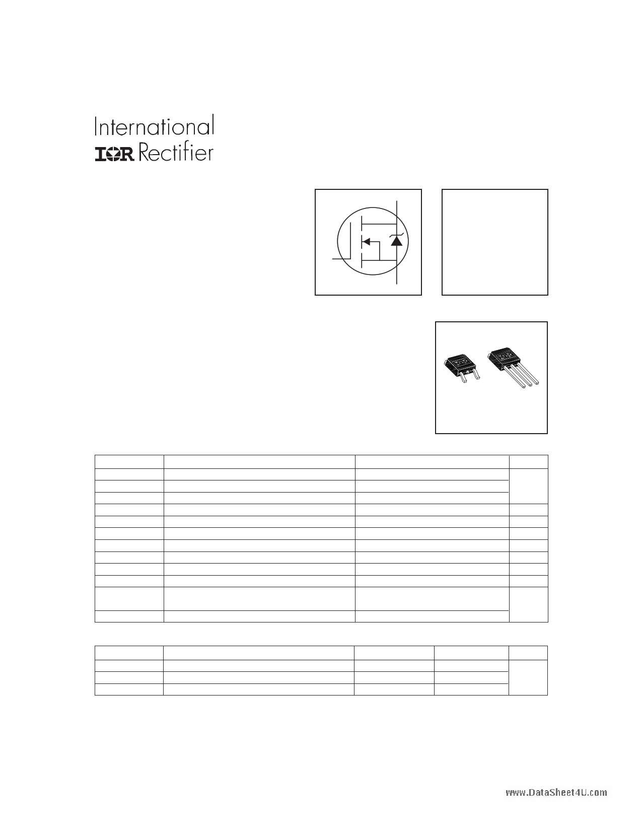
PD- 91334E HEXFETPower MOSFET l Logic-Level Gate Drive l Ultra Low On-Resistance l Surface Mount (IRLR2905) l Straight Lead (IRLU2905) l Advanced Process Technology l Fast Switching l Fully Avalanche Rated G VDSS = 55V RDS(on) = 0.027Ω ID = 42A S ID @ TC = 25°C ID @ TC = 100°C IDM PD @TC = 25°C VGS EAS IAR EAR dv/dt TJ TSTG Parameter Continuous Drain Current, VGS @ 10V Continuous Drain Current, VGS @ 10V Pulsed Drain Current Power Dissipation Single Pulse Avalanche Energy Avalanche Current Repetitive Avalanche Energy Peak Diode Recovery dv/dt Operating Junction and 42 30 RθJC RθJA RθJA Junction-to-Case |
|
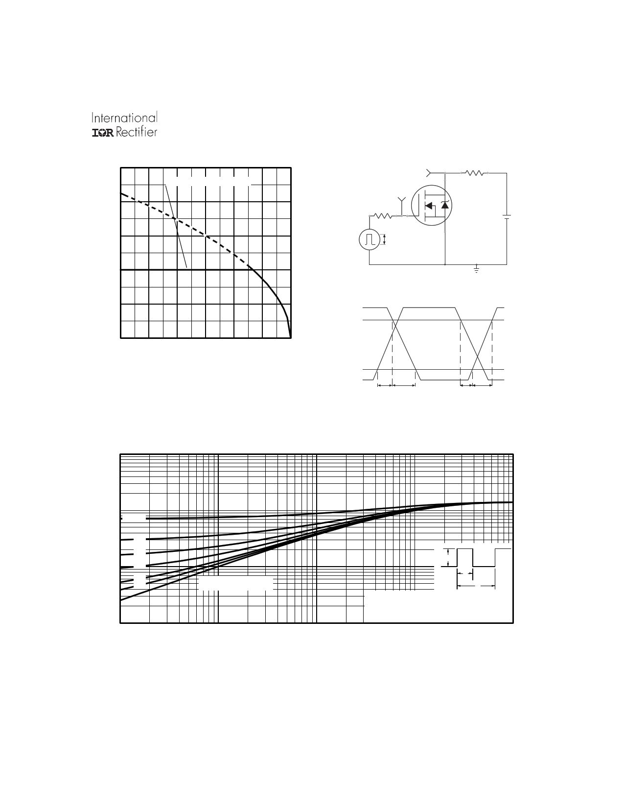
25 50 75 100 125 150 175 TC , Case Temperature ( °C) Fig 9. Maximum Drain Current Vs. Case Temperature VDS VGS RG RD D.U.T. Pulse Width ≤ 1 µs Duty Factor ≤ 0.1 % +-VDD Fig 10a. Switching Time Test Circuit VDS 90% VGS td(on) tr td(off) tf Fig 10b. Switching Time Waveforms 1 0.1 0.05 0.02 PDM SINGLE PULSE t1 t2 0.0001 1. Duty factor D = t1 / t 2 2. Peak T J = P DM x Z thJC + TC 0.001 t1, Rectangular Pulse Duration (sec) 0.01 Fig 11. Maximum Effective Transient Thermal Impedance, Junction-to-Case www.irf.com Preview 5 Page |
|
On this page, you can learn information such as the schematic, equivalent, pinout, replacement, circuit, and manual for IRLR2905 electronic component. |
| Information | Total 10 Pages |
| Link URL | |
| Download |
Share Link :
Electronic Components Distributor
|
An electronic components distributor is a company that sources, stocks, and sells electronic components to manufacturers, engineers, and hobbyists. |
| SparkFun Electronics | Allied Electronics | DigiKey Electronics | Arrow Electronics |
| Mouser Electronics | Adafruit | Newark | Chip One Stop |


 50
50


