TIP120 vs TIP31 vs IRF530
In the table below we try to compare TIP120, TIP31, and TIP122 transistors, the electrical specification comparison is really helpful for circuit making.
| Characteristics | TIP120 | TIP31 | TIP122 |
|---|---|---|---|
| Collector to base voltage (VCB) | 60V | 40V | 100V |
| Collector to emitter voltage (VCE) | 60V | 40V | 100V |
| Emitter to base voltage (VEB) | 5V | 5V | 5V |
| Collector to emitter saturation voltage (VCE (SAT)) | 2V to 4V | 1.2V | 2V to 4V |
| Collector current (IC) | 5A | 3A | 5A |
| Power dissipation | 65W | 40W | 65W |
| Junction temperature (TJ) | -65 to +150°C | -65 to +150°C | -55 to +150°C |
| Transition frequency (FT) | — | 3MHZ | — |
| Gain (hFE) | 1000hFE | 25 to 50hFE | 1000hFE |
| Package | TO-220 | TO-220 | TO-220 |
Almost many of the electrical specifications of TIP120, TIP122, and TIP31 transistors are the same.
The DC current gain value of TIP120 and TIP122 transistors is the same and TIP31 is less, this is why both these transistors had amplifier and driver applications.
Datasheets
Просмотр и загрузка
Datasheet TIP120, TIP121, TIP122 (NPN); TIP125, TIP126, TIP127 (PNP)
PDF, 296 Кб, Язык: анг., Версия: 9, Файл закачен: 29 июл 2021, Страниц: 8Plastic Medium-Power Complementary Silicon Transistors
Выписка из документа
TIP120, TIP121, TIP122
(NPN); TIP125, TIP126,
TIP127 (PNP)
Plastic Medium-Power
Complementary Silicon
Transistors www.onsemi.com Designed for general−purpose amplifier and low−speed switching
applications.
Features • High DC Current Gain − = 2500 (Typ) @ IC
= 4.0 Adc
Collector−Emitter Sustaining Voltage − @ 100 mAdc
VCEO(sus) = 60 Vdc (Min) − TIP120, TIP125
= 80 Vdc (Min) − TIP121, TIP126
= 100 Vdc (Min) − TIP122, TIP127
Low Collector−Emitter Saturation Voltage −
VCE(sat) = 2.0 Vdc (Max) @ IC = 3.0 Adc
= 4.0 Vdc (Max) @ IC = 5.0 Adc
Monolithic Construction with Built−In Base−Emitter Shunt Resistors
Pb−Free Packages are Available*
hFE • •
•
• DARLINGTON
5 AMPERE
COMPLEMENTARY SILICON
…
Просмотр и загрузка
Datasheet TIP120, TIP121, TIP122
PDF, 289 Кб, Язык: анг., Версия: 2, Файл закачен: 29 июл 2021, Страниц: 5NPN Epitaxial Darlington Transistor
Выписка из документа
Equivalent Circuit
C Features
• Medium Power Linear Switching Applications
• Complementary to TIP125 / TIP126 / TIP127 B R1 TO-220 1 1.Base 2.Collector 3.Emitter R2 R1 ≅ 8kΩ
R2 ≅ 0.12kΩ E Ordering Information
Part Number Top Mark Package Packing Method TIP120 TIP120 TO-220 3L (Single Gauge) Bulk TIP120TU TIP120 TO-220 3L (Single Gauge) Rail TIP121 TIP121 TO-220 3L (Single Gauge) Bulk TIP121TU TIP121 TO-220 3L (Single Gauge) Rail TIP122 TIP122 TO-220 3L (Single Gauge) Bulk TIP122TU TIP122 TO-220 3L (Single Gauge) Rail Absolute Maximum Ratings
Stresses exceeding the absolute maximum ratings may damage the device. The device may not function or be operable above the recommended operating conditions and stressing the parts to these levels is not recommended. In addition, extended exposure to stresses above the recommended operating conditions may affect device reliability. The
absolute maximum ratings are stress ratings only. Values are at TC = 25°C unless otherwise noted. Symbol
VCBO Parameter
Collector-Base Voltage Value
TIP120 60 TIP121 80 TIP122 100 TIP120 60 TIP121 80 TIP122 100 Unit
V VCEO Collector-Emitter Voltage V VEBO Emitter-Base Voltage 5 V IC Collector Current (DC) 5 A ICP Collector Current (Pulse) 8 A IB Base Current (DC) 120 mA TJ Junction Temperature 150 °C -65 to 150 °C TSTG Storage Temperature Range 2001 Semiconductor Components Industries, LLC.
November-2017, Rev.2 Publication Order Number:
TIP122/D TIP120 / TIP121 / TIP122 — NPN Epitaxial Darlington Transistor TIP120 / TIP121 / TIP122
NPN Epitaxial Darlington Transistor Values are at TC = 25°C unless otherwise noted. Symbol
PC Parameter Value Collector Dissipation (TA = 25°C) 2 Collector Dissipation (TC = 25°C) 65 Unit
W Electrical Characteristics
Values are at TC = 25°C unless otherwise noted. Symbol Parameter Conditions VCEO(sus) ICEO Collector-Emitter Sustaining
TIP121
Voltage
TIP122
Collector Cut-Off Current ICBO Collector Cut-Off Current IEBO Emitter Cut-Off Current hFE DC Current Gain(1) Max. IC = 100 mA, IB = 0 Unit 80 V 100 TIP120 VCE = 30 V, IB = 0 0.5 TIP121 VCE = 40 V, IB = 0 0.5 TIP122 VCE = 50 V, IB = 0 0.5 TIP120 VCB = 60 V, IE = 0 0.2 TIP121 VCB = 80 V, IE = 0 0.2 TIP122 VCB = 100 V, IE = 0 0.2 VEB = 5 V, IC = 0 2 VCE = 3 V, IC = 0.5 A 1000 VCE = 3 V, IC = 3 A 1000 mA mA
mA IC = 3 A, IB = 12 mA 2.0 IC = 5 A, IB = 20 mA 4.0 Base-Emitter On Voltage(1) VCE = 3 V, IC = 3 A 2.5 V Output Capacitance VCB = 10 V, IE = 0,
…
TIP120 transistor electrical specification description
In this section, we try to explain the electrical specifications of the TIP120 transistor, which is helpful in the replacement process.
Voltage specs
The terminal voltage specs of the TIP120 transistor are collector to emitter and collector to base voltage is 60V and emitter to base voltage is 5V, the voltage values show it is a medium power device.
Collector to emitter saturation voltage is 2V to 4V, it is the voltage value needed for switching.
Current specs
Collector current is 5A, the current value of the transistor shows the load capacity of the device, TIP120 is a transistor having higher capacity.
Dissipation specs
The power dissipation at the TIP120 transistor is 65W, the device dissipation mainly depends on the transistor package and overall capacity.
Current gain specs
The current gain value of TIP120 is 1000hFE, the DC current value shows that it is capable of amplifier and driver applications.
The small-signal current gain value of the TIP120 transistor is 4hFE, so in small-signal applications, the TIP120 transistor had poor current gain.
TIP120 transistor characteristics
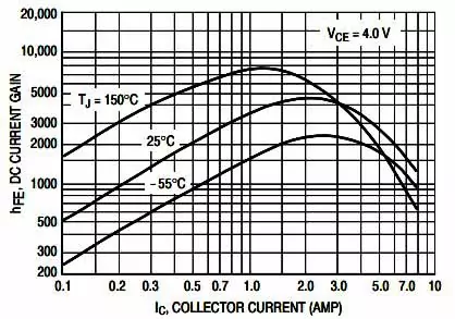
 DC current gain characteristics of the TIP120 transistor
The figure shows the DC current gain characteristics of the TIP120 transistor, the graph is plotted with DC current gain vs collector current.
At the fixed collector to emitter voltage, the gain value increases from a low value to a higher one and decreases at the end with respect to collector current.
The gain value variations will be also reflected at the junction temperature of the device.
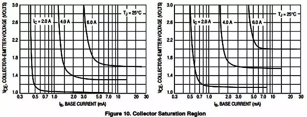
 collector to emitter saturation voltage characteristics of the TIP120 transistor
The figure shows the collector to emitter saturation voltage characteristics of the TIP120 transistor, the graph is plotted with the collector to emitter saturation vs base current.
The graphical variations are been plotted with different collector current values, the saturation value is almost fixed, and the base current varies.


